

Best Stamping Parts for Durable and Precise Metal Fabrication
2026-11-16
Ask a production engineer what goes wrong with stamped metal parts, and the answer is rarely a single dramatic failure. It’s the slow drift: burrs that appear as tooling wears, springback that moves a hole position by a fraction of a millimeter, or a batch that passes inspection but fails after assembly. The best stamping parts for durable, precise metal fabrication don’t earn that reputation from a material certificate alone. That reputation comes from how parts are designed, tooled, and controlled over thousands of cycles. In this guide, we break down what to look for — and how BOYIKUN builds that consistency into every run.
Where Stamped Parts Gain Their True Accuracy
Accuracy in stamped parts rarely comes from press tonnage alone. The real location of precision is usually in the die shut height, the clearance between guide posts and bushings, and the way the material springs back after cutting. A part can be dimensionally correct on the drawing and still shift by a few hundredths of a millimeter when a different coil of steel arrives on the line.
During continuous production, stability matters more than the nominal dimensions of a single setup. Feed pitch repeatability, changes in lubricant coverage, and the condition of cutting edges all move the final measurement point. A slightly dull punch or a minor buildup of zinc flakes can change the shear zone enough to be seen in a capability chart, which is why experienced operators make small adjustments after the first few dozen hits instead of relying on a fixed parameter sheet.
The last real gain in accuracy usually happens after forming, through measurement and reverse compensation. Wrinkling, thinning, and springback vary with temper, coating thickness, and even the warm-up cycle of the press, so holding a tight tolerance depends on short-loop correction rather than locking every setting at the start of a run. In many cases, repeatable die location and thermal drift have a greater effect on final part consistency than the complexity of the tooling itself.
Material Choices That Outlast the Assembly Around Them
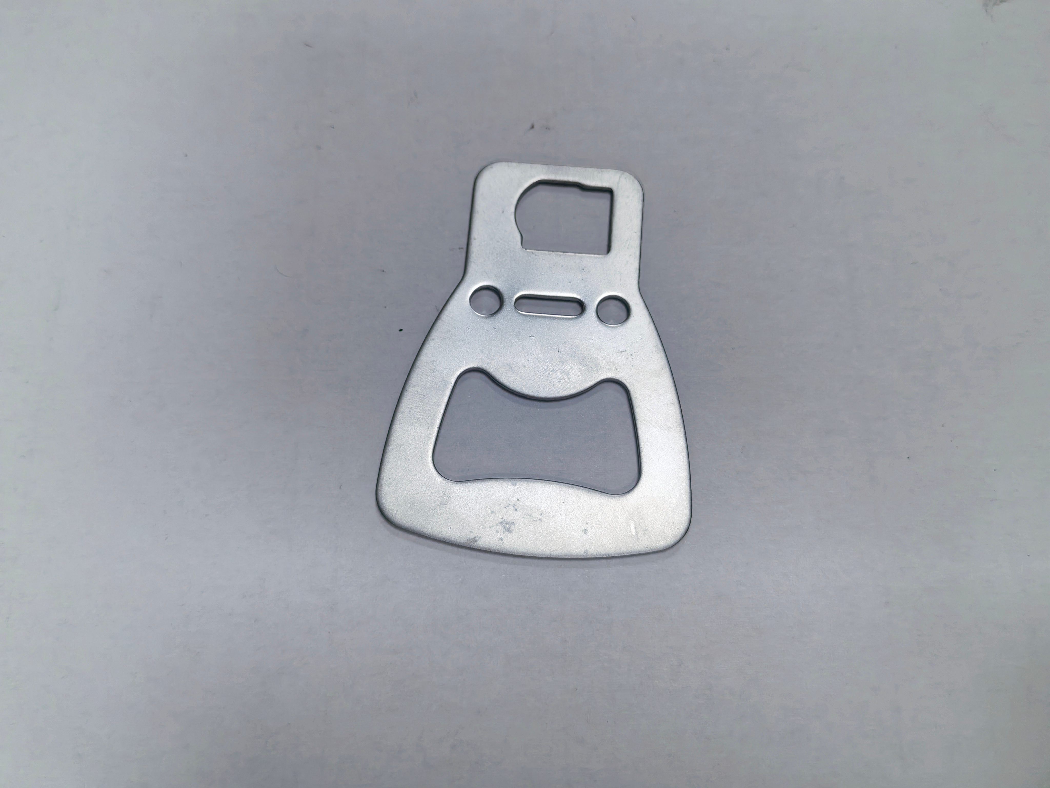
A cast bronze hinge will usually outlive the wooden door it swings and the steel screws holding it in place. That mismatch is not a flaw to hide; it is a signal to design joints so the long-lived part can be removed, serviced, or salvaged without destroying the shorter-lived assembly. Threaded brass inserts pressed into plywood, stainless springs inside a polymer latch, or a solid copper bushing seated in an aluminum bracket all follow the same logic: let the durable material carry the wear, and make the surrounding structure easier to replace.
The trouble starts when a high-performance material is bonded into a short-lived product with no thought for separation. An elastomer seal rated for decades can end up glued into a housing that cracks after a few seasons, taking the seal with it. A better approach is to choose mechanical retention or reversible adhesives, so the component that actually survives can be reused or inspected. This flips the usual priority: instead of asking only whether a material meets the product's lifespan, ask whether the product can gracefully fall away from the material.
Material spec sheets rarely capture this kind of durability because they measure the material in isolation, not the life of the assembly around it. Yet field failures often show exactly that pattern: the zinc casting corrodes while its stainless pivot remains smooth, or the glass-filled nylon housing embrittles while the ceramic bearing inside still spins freely. Designing for that reality means accepting that some parts should be treated as permanent and detailing their connections so they can be reclaimed later.
Tooling Habits That Keep Dimensions Stable Over Time
Most shops fight size drift by chasing offsets after the fact, but the ones that hold tolerance consistently treat tooling setup as a warm-up routine rather than a one-time adjustment. We run a short cycle with a known bar or gauge pin before first-piece inspection, compare that reading to yesterday’s shutdown value, and only then decide whether a tool offset actually needs to move. This catches thermal growth and spindle bearing warm-up before they get baked into a bad correction. Keeping a small handwritten log or a simple spreadsheet of those morning readings shows drift patterns that a single measurement never reveals.
Clamping repeatability matters just as much as cutting edges. A slightly dirty collet, a torque wrench that someone set by feel, or a fixture jaw with a shiny wear spot can shift a feature location by more than the total tolerance band. We number the contact faces, clean them at every setup, and use the same pull-stud torque for every tool change. When a bore starts trending oval or a shoulder starts tapering a few microns, the first place we look is not the program but the interface between the tool holder and the spindle nose.
Tool life is easier to manage when you stop treating it as a fixed part count. We track the last few measured diameters on a run chart and watch the slope of wear, then swap inserts just before that slope starts to curve upward. It feels early, but it avoids the late-shift panic where someone applies a large tool offset to compensate for a worn edge and then the next new tool cuts oversize. Stable dimensions come from making small, boring adjustments on a schedule, not from heroic corrections after a bad part.
Edge Quality Details That Prevent Assembly Failures
Burrs, micro-cracks, and inconsistent chamfer angles along a board edge often go unnoticed until a connector refuses to seat or a guide pin snaps during final assembly. Paying attention to how the raw laminate is routed, not just what the final dimensions measure, makes the difference between a quiet production line and a stack of rejected units. A clean edge with a slight, uniform bevel allows mating parts to slide into place without shaving off fiberglass dust that can contaminate nearby contacts.
The tolerance stack between panel edges and mounting brackets is rarely the primary failure point—what actually causes trouble is the way edge plating wears under repeated insertion. Thin copper at the board perimeter can lift or crack if the edge was over-polished to hide tool marks. Inspecting cross-sections under magnification reveals whether the plating wraps far enough around the radius to survive assembly torque and thermal cycling.
For high-volume builds, edge quality should be specified in the fabrication notes as a measurable finish, not a vague instruction like "deburr all edges." Ask for a sample coupon from the panel border with each batch so you can check for tear-out, resin smear, and copper nodules before the boards reach the assembly floor. Small details here save hours of troubleshooting later.
Surface Treatments That Add Years Beyond Basic Rust Protection
A thick hot-dip galvanized layer does more than sit on the surface. The zinc reacts with the steel to form intermetallic alloy layers that are harder than the base metal, and if the coating gets scratched, the surrounding zinc sacrifices itself to keep the exposed edge from rusting. Galvanized guardrails and transmission towers routinely outlast their original paint systems by a decade or more for exactly this reason.
Powder coating and ceramic-filled finishes hold up in places where moisture, salt spray, and UV tear through ordinary primers. A properly cured powder film seals edges and corners that wet paint tends to miss, while some ceramic additives create a dense, low-friction surface that sheds water and road grime instead of holding it against the metal.
For fasteners, brackets, and aluminum parts, conversion coatings like phosphate or anodizing create a stable base layer that stops corrosion from creeping under the topcoat. Anodized aluminum, for instance, grows an oxide skin from the metal itself, so chips and nicks do not open a direct path to raw material the way they do with a simple sprayed-on finish.
Keeping Repeatability Tight from First Prototype to Final Production
Repeatability often starts slipping long before anyone notices. In the prototype phase, a few microns of drift or a slightly inconsistent cure cycle can hide behind the excitement of getting a first part out. But those early variations rarely disappear on their own; they embed themselves into the tooling, the fixturing, and the tacit assumptions of the build process. Locking down repeatability means treating the prototype not as a rough draft, but as the first real data point. Every adjustment made at this stage should be recorded with the same seriousness as a production change order.
As the design moves toward final production, the challenge shifts from capturing variability to predicting it. Materials from a new supplier, a different operator on the line, or even a seasonal shift in shop humidity can all push a previously stable process off target. Tight repeatability comes from building small, deliberate constraints into each handoff: nominal dimensions with one-sided tolerances where they matter, fixture pins that only fit one way, and inspection routines that sample the first three parts after any setup change. These details sound minor, but they prevent the slow creep that turns a good prototype into an unreliable product.
What separates teams that hold repeatability from those that chase it is the habit of measuring the same thing the same way every time. Instead of relying on a final functional test to catch drift, they track a handful of early indicators throughout the build. If a bearing press force rises by eight percent, someone investigates before the lot is finished. If a curing oven takes four minutes longer to reach temperature on a cold morning, the cycle is adjusted and verified rather than ignored. Repeatability is not a single setting or a magic parameter; it is a chain of small, boring decisions repeated from the first prototype until the last production unit ships.
FAQ
Stainless steel and high-strength carbon steel are usually the first choices for tough environments. Brass and copper alloys work well for electrical parts, while aluminum makes sense when weight matters more than raw strength.
Many shops can hold tolerances around plus or minus 0.05 mm on well-designed features. With tighter tooling and secondary operations, even finer tolerances are possible, but the part geometry and material springback will set the practical limit.
It depends on the part, but the break-even point is often lower than people expect. Once the tooling is built, the per-piece cost drops sharply, so medium to high production runs usually justify the upfront investment without much trouble.
Common options include zinc plating, nickel plating, powder coating, passivation for stainless steel, and anodizing for aluminum. The right finish depends on corrosion exposure, appearance requirements, and whether the part needs to conduct electricity.
If the part starts as sheet metal and will be produced in volume, stamping is usually faster and less expensive per unit. Machining makes more sense for thick blocks, very low quantities, or features that simply cannot be formed with a die.
Yes, progressive and compound dies can produce fairly complex geometries in a single process. The key is designing the part so the features can be formed in sequence without the material tearing or distorting.
Most projects take a few weeks for tooling design, machining, and tryout, though very complex dies can take longer. If the design is stable and materials are available, first article parts are often ready within four to six weeks.
Thickness affects the required die clearance, minimum bend radius, and how much springback to expect after forming. Thicker stock can carry more load but may need larger radii and more generous tolerances, while thin stock allows finer details but can be harder to keep flat.
Conclusion
Precision in stamped parts rarely comes from a single setting on a press. It starts with how the strip is positioned, how the dies are aligned under load, and how quickly the tooling recovers after each hit. Shops that hold tight tolerances tend to watch the entire forming sequence rather than just the final dimension: pilot release timing, pad pressure, and stripper travel all influence whether a hole lands where it should. Material choice matters just as much. A well-chosen stainless steel or high-strength copper alloy can keep its shape long after surrounding components have loosened, but only if the grain direction and temper are matched to the bend radii and load direction. Over time, tooling habits make the difference between a process that drifts and one that stays predictable. Regular inspection of punches, trimming edges, and guide pins keeps the die set from developing the small clearances that turn into taper, twist, or dimensional creep.
What happens at the cut edge often decides whether an assembly goes together cleanly. A slight rollover or a hidden burr may not look serious on a sample, but in a mating feature it can cause misalignment, galling, or premature wear. Consistent edge quality means monitoring sharpness, clearance, and lubrication as a system, not as isolated checklist items. Surface preparation extends that mindset. Rather than stopping at basic rust protection, long-life parts benefit from treatments chosen for the actual environment: passivation for stainless, zinc-nickel for corrosion-prone brackets, or dry-film coatings where torque retention matters. None of this matters if the first prototype behaves differently from the ten-thousandth part. Keeping repeatability tight requires locking down setup data, measuring key features during the run, and adjusting only when the data shows a real shift. That combination of disciplined tooling, material awareness, and in-process verification is what separates durable stampings from parts that simply look right on a drawing.
Contact Us
Contact Person: Xianchen Hu
Email: [email protected]
Tel/WhatsApp: 86-13248645200
Website: https://www.hexnb.com/