

How Does a Hydraulic Lift Cylinder Eliminate Wobbling and Jamming?
2026-09-17
1. What Are the Root Causes of Wobbling and Jamming in a Hydraulic Lift Cylinder?
Wobbling and jamming in a Hydraulic Lift Cylinder can be traced to four root causes. The first is side loading. If the load is not perfectly centered on the cylinder rod, a bending moment is created. This bending moment causes the rod to deflect sideways, which increases the friction on the rod seal and the piston. The result is erratic motion, known as stick-slip or wobbling. The second cause is buckling. When a Hydraulic Lift Cylinder is fully extended, the rod acts as a column. If the rod diameter is too small for the extended length, the rod can buckle under compressive load. Buckling causes the rod to bend, which leads to jamming and potential permanent deformation. The third cause is seal friction. The rod seal and the piston seal must maintain contact with the moving surfaces to prevent leakage. If the seal is too tight or the surface finish is too rough, the friction increases, causing the motion to become jerky. The fourth cause is inadequate guiding. The rod bearing and the piston guide ring must maintain the alignment of the rod and piston within the cylinder bore. If the guide rings are worn or undersized, the rod can tilt, causing the piston to rub against the bore.
Diagnostic tip: If the wobbling occurs only at the beginning of the stroke, the problem is likely side loading. If it occurs at full extension, the problem is likely buckling. If it occurs throughout the stroke, the problem is likely seal friction or guiding.
Raydafon Technology Group Co.,Limited has been manufacturing Hydraulic Lift Cylinder units for over 15 years. Our factory has developed a set of design standards that address each of these root causes. The following sections explain the design features and how they are verified.
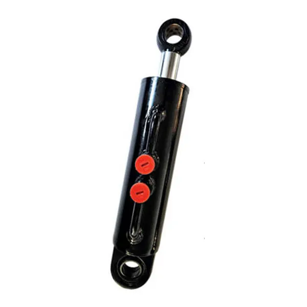
2. How Does Rod Diameter and Buckling Resistance Prevent Jamming at Full Extension?
Buckling is the most common cause of jamming in a Hydraulic Lift Cylinder that is used in a vertical application, such as a scissor lift or a dock leveler. The buckling load depends on the rod diameter, the extended length, and the end conditions. The Euler buckling formula is used to calculate the critical load. For a given load and extended length, the required rod diameter can be determined. The table below shows the maximum extended length for different rod diameters at a compressive load of 100 kN, assuming pinned-pinned end conditions.
| Rod diameter (mm) | Maximum extended length (mm) at 100 kN | Safety factor 2.0 | Safety factor 3.0 |
| 40 | 1,200 | 850 | 700 |
| 50 | 1,800 | 1,270 | 1,040 |
| 63 | 2,800 | 1,980 | 1,620 |
| 80 | 4,500 | 3,180 | 2,600 |
| 100 | 7,000 | 4,950 | 4,040 |
In our factory, we recommend a minimum safety factor of 2.0 for the buckling calculation. For applications with dynamic loads or off-center loading, a safety factor of 3.0 is preferred. Our Hydraulic Lift Cylinder units are available with rod diameters from 40 mm to 150 mm. We also offer a hollow rod option for applications where weight is a concern. The hollow rod has a larger outer diameter for the same weight, which increases the buckling resistance.
3. How Do Guide Rings and Rod Bearings Eliminate Side Load Wobbling?
Side loading is the most common cause of wobbling in a Hydraulic Lift Cylinder. The side load can come from an off-center load, a misaligned mounting, or a structural deflection of the machine frame. The guide rings and the rod bearing are the components that resist side loading and maintain alignment. The guide ring is a wear ring that is installed on the piston. It has a low friction coefficient and a high load capacity. It maintains the piston centered in the bore, preventing metal-to-metal contact. The rod bearing is installed in the cylinder head. It supports the rod and absorbs the side load. The length of the rod bearing determines the side load capacity. A longer bearing reduces the contact stress and provides better guidance. The table below shows the side load capacity of our Hydraulic Lift Cylinder units with different rod bearing lengths.
| Rod diameter (mm) | Rod bearing length (mm) | Max side load (N) | Max side load with 2x bearing length (N) |
| 40 | 40 | 1,200 | 2,100 |
| 50 | 50 | 1,800 | 3,200 |
| 63 | 63 | 2,800 | 5,000 |
| 80 | 80 | 4,500 | 8,000 |
| 100 | 100 | 7,000 | 12,500 |
Raydafon Technology Group Co.,Limited uses a proprietary bronze alloy for the rod bearing and a PTFE composite for the guide ring. The bronze bearing provides high load capacity and good wear resistance. The PTFE guide ring provides low friction and prevents stick-slip. In our factory, we test every Hydraulic Lift Cylinder for side load capacity by applying a known side load and measuring the deflection and the friction force.
4. What Role Does Seal Design Play in Preventing Stick-Slip and Jamming?
Seal friction is a major contributor to stick-slip, which is experienced as a jerky or uneven motion. The rod seal and the piston seal must maintain contact with the moving surfaces to prevent leakage. However, if the friction is too high, the seal will grip the surface and then release suddenly, causing the motion to jump. The key to preventing stick-slip is to use a seal material with a low friction coefficient and a geometry that maintains a stable lubricating film. Our Hydraulic Lift Cylinder units use a polyurethane rod seal with a double lip design. The primary lip seals the pressure, and the secondary lip provides stability. The seal is energized by a stainless steel spring, which maintains constant contact force even at low pressure. The piston seal is a PTFE-based composite with a bronze filler for wear resistance. The table below shows the friction characteristics of our seal system compared to standard seals.
| Seal type | Static friction (N) | Dynamic friction (N) | Stick-slip tendency |
| Standard nitrile U-cup | 85 | 45 | High |
| Polyurethane double lip (our standard) | 52 | 38 | Low |
| PTFE composite with spring | 35 | 32 | Very low |
Our factory has tested these seals on a hydraulic test bench at pressures from 10 bar to 350 bar and speeds from 0.01 m/s to 0.5 m/s. The polyurethane double lip seal showed no stick-slip at speeds above 0.05 m/s. The PTFE composite seal showed no stick-slip even at 0.01 m/s.
Frequently Asked Questions About Hydraulic Lift Cylinder Wobbling and Jamming
Summary for Maintenance Engineers
Wobbling and jamming in a Hydraulic Lift Cylinder are not inevitable. They are the result of specific design and application factors that can be controlled. The key factors are rod diameter for buckling resistance, guide ring and rod bearing design for side load capacity, and seal design for low friction and stick-slip prevention. When selecting a cylinder, verify the buckling safety factor, the side load capacity, and the seal friction characteristics. When troubleshooting, isolate the cylinder from the machine to identify the root cause. Raydafon Technology Group Co.,Limited has been manufacturing Hydraulic Lift Cylinder units for over 15 years and provides full technical support for selection and troubleshooting.
Raydafon Technology Group Co.,Limited manufactures Hydraulic Lift Cylinder units with rod diameters from 40 mm to 150 mm, side load capacities up to 12,500 N, and low-friction seal systems. We provide buckling calculations and side load capacity charts for each application.