

What Makes Hydraulic Lift Cylinders Ideal for Industrial Machinery?
2026-09-15
1. How Does the Power Density of a Hydraulic Lift Cylinder Compare to Electric and Pneumatic Alternatives?
Power density is the amount of force a device can generate per unit of volume or weight. A Hydraulic Lift Cylinder operates at pressures of 100 to 350 bar (1,450 to 5,000 psi). At 200 bar, a cylinder with a 100 mm bore generates a force of approximately 157 kN (about 16 tonnes). To generate the same force with a pneumatic cylinder at 7 bar, the bore would need to be more than 500 mm. To generate the same force with an electric actuator, the motor and gearbox would be significantly larger and heavier. This high power density is the primary reason why hydraulic systems dominate in heavy industrial machinery.
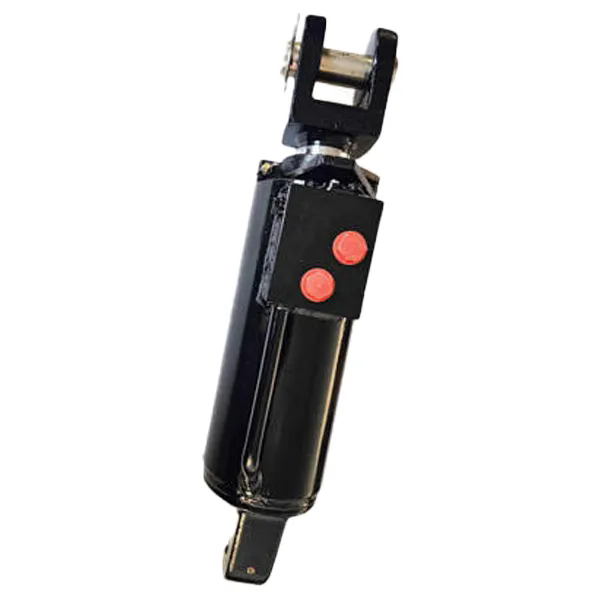
The table below compares the force density of the three technologies.
| Technology | Typical operating pressure | Force from 100 mm bore (or equivalent) | Weight of actuator (approx.) | Force-to-weight ratio |
| Hydraulic Lift Cylinder | 200 bar | 157 kN | 25 kg | 6.3 kN/kg |
| Pneumatic cylinder | 7 bar | 5.5 kN | 8 kg | 0.7 kN/kg |
| Electric actuator (ball screw) | N/A | 30 kN (typical max) | 45 kg | 0.7 kN/kg |
The force-to-weight ratio of a Hydraulic Lift Cylinder is roughly ten times higher than that of a pneumatic cylinder or an electric actuator. This means that a hydraulic system can lift a heavier load with a smaller, lighter actuator. In industrial machinery where space is limited and weight affects structural design, this is a decisive advantage. Raydafon Technology Group Co.,Limited manufactures Hydraulic Lift Cylinder units with bore diameters from 40 mm to 320 mm and pressure ratings up to 350 bar.
2. Why Does a Hydraulic Lift Cylinder Handle Variable and Shock Loads Better Than Other Technologies?
Industrial lifting applications rarely involve a constant load. A die cart may lift a mold that is heavier on one side. A press brake may encounter a sudden resistance if the material is thicker than expected. A foundry ladle may experience a shock load when the molten metal shifts. A Hydraulic Lift Cylinder handles these variable and shock loads because hydraulic fluid is incompressible. When a shock load occurs, the hydraulic fluid transmits the force instantly to the relief valve, which limits the pressure and protects the system. A pneumatic cylinder, by contrast, compresses the air under shock loads, which causes a bouncing or springy motion that can damage the load or the machine. An electric actuator may stall or trip the motor under shock loads. The table below compares the response of the three technologies to shock loads.
| Shock load scenario | Hydraulic Lift Cylinder | Pneumatic cylinder | Electric actuator |
| Sudden 50% load increase | Relief valve opens, system pressure limited, no damage | Air compresses, cylinder bounces, position error | Motor stalls or trips, position lost |
| Sudden load removal | Check valve holds position, controlled descent | Cylinder extends rapidly, possible impact | Brake engages, but wear increases |
| Off-center load | Rod bearing handles side load, cylinder continues | Seal wears rapidly, cylinder may bind | Screw and nut wear rapidly |
Raydafon designs Hydraulic Lift Cylinder units with cushioning at the end of stroke and with rod bearings that are sized to handle side loads. These features are essential for industrial machinery where the load is not perfectly centered and where shock loads are common.
3. What Are the Key Design Features of a Hydraulic Lift Cylinder for Industrial Use?
The design of a Hydraulic Lift Cylinder for industrial machinery differs from a standard cylinder in several important ways. The table below summarizes the key features and their benefits.
| Design feature | Specification | Benefit for industrial machinery |
| Bore diameter range | 40 mm to 320 mm | Matches the force requirement of the application |
| Rod diameter range | 20 mm to 220 mm | Resists buckling under compression loads |
| Working pressure | Up to 350 bar | Provides high force from a compact package |
| Rod surface finish | Chrome plated, 0.2 – 0.4 µm Ra | Resists corrosion and wear |
| Rod hardness | 55 – 62 HRC | Resists scratches and impact damage |
| Seal type | Polyurethane U-cup with anti-extrusion ring | Handles high pressure and shock loads |
| Operating temperature | -30°C to +120°C | Suitable for foundry and outdoor applications |
| Cushioning | Adjustable at both ends | Reduces shock at end of stroke |
| Mounting options | Clevis, flange, trunnion, spherical bearing | Adapts to different machine designs |
Our factory tests every Hydraulic Lift Cylinder to 1.5 times the rated working pressure and performs a 10,000-cycle endurance test before shipping. This ensures that the cylinder will perform reliably in the most demanding industrial applications.
4. How Does Maintenance and Service Life Compare Across the Three Technologies?
Maintenance is a critical factor in the total cost of ownership of any industrial lifting system. A Hydraulic Lift Cylinder requires periodic inspection of the seals and the hydraulic fluid, but the cylinder itself can last 10 to 15 years with proper care. A pneumatic cylinder has a shorter seal life because the air is often contaminated with moisture and oil, which degrades the seals. An electric actuator has a finite life determined by the ball screw and the motor bearings, and it may require replacement after 3 to 5 years of heavy use. In our factory, we have Hydraulic Lift Cylinder units that have been in service for over 20 years with only seal replacements. The key is to maintain the hydraulic fluid cleanliness and to replace the seals at the recommended interval.
Maintenance interval for our Hydraulic Lift Cylinder: Inspect seals every 2,000 hours or 12 months. Replace seals every 5,000 hours or 3 years. Check rod surface for scratches at every inspection. Maintain hydraulic fluid cleanliness to ISO 4406 code 18/16/13.
Frequently Asked Questions About Hydraulic Lift Cylinders in Industrial Machinery
Summary for Equipment Engineers and Maintenance Managers
The Hydraulic Lift Cylinder is the ideal choice for industrial machinery because of its high power density, its ability to handle variable and shock loads, and its long service life. It is not the right choice for every application—light loads and clean environments may be better served by electric or pneumatic actuators. But for heavy loads, high cycle rates, and harsh conditions, the hydraulic solution is unmatched. Raydafon Technology Group Co.,Limited has been manufacturing Hydraulic Lift Cylinder units for over 20 years and supplies to industrial machinery builders worldwide.
Raydafon Technology Group Co.,Limited manufactures Hydraulic Lift Cylinder units in a full range of bore sizes, rod diameters, and mounting configurations. We provide full technical data, including force calculations, buckling analysis, and seal life estimates.