

Why Are Precision Gears Essential for High Accuracy Motion Control?
2026-08-26
1. How Does Backlash Become the Dominant Error Source in a Motion Loop?
Backlash is the lost motion when the gear direction reverses. In a typical spur gear with standard quality (AGMA 8), backlash can be 8 to 12 arc minutes. In a motion control application that requires bi directional positioning—such as a milling machine cutting a contour—this backlash causes a dead zone in the control loop. The motor rotates, but the load does not move until the gear teeth re engage. Our factory measures backlash on every Precision Gear using a high resolution encoder and a torque arm. For a gear pair with AGMA 10 quality, we achieve backlash below 2 arc minutes. For ground helical gears, we can reach 1 arc minute or less.
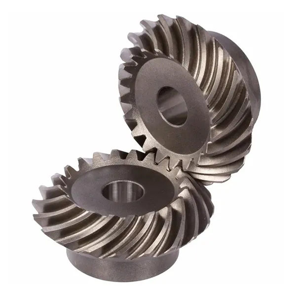
The table below shows the real world positioning error caused by different levels of backlash in a typical ball screw feed system.
| Gear quality level (AGMA) | Typical backlash (arc minutes) | Positioning error at 10 mm travel (µm) | Application suitability |
| AGMA 8 (standard hobbed) | 8 – 12 | 18 – 25 | General purpose, low accuracy |
| AGMA 10 (ground) | 2 – 4 | 5 – 8 | Precision machining, robotics |
| AGMA 12 (super ground) | < 1.5 | < 3 | Semiconductor, medical, aerospace |
| Our Precision Gear (AGMA 12 equivalent) | 1.0 – 1.5 | 2.0 – 2.5 | High end motion control |
One of our customers, a manufacturer of pick and place machines, replaced standard gears with our Precision Gear and saw their placement accuracy improve from 0.05 mm to 0.015 mm. The reduction in backlash was the primary reason. The servo tuning time was also reduced by 40 percent because the control loop no longer had to compensate for the dead zone. This is why backlash is not a mechanical nuisance—it is a control system problem, and a Precision Gear is the solution.
2. Why Does Transmission Error Cause Velocity Ripple at Low Speeds?
Transmission error is the difference between the theoretical and actual output position of a gear pair during a full revolution. It arises from tooth profile deviations, pitch errors, and runout. At high speeds, the inertia of the system can smooth out these errors. But at low speeds—such as when a machine tool is finishing a surface—transmission error manifests as velocity ripple. The motor tries to maintain a constant speed, but the load speed fluctuates because the gear ratio is not perfectly constant. This leaves visible chatter marks on the machined surface. Our factory measures transmission error using a double flank test and a single flank test. For our Precision Gear, we hold the single flank transmission error to within 0.3 arc minutes peak to peak. The table below shows how different gear qualities affect the velocity ripple in a typical 100 RPM feed application.
| Gear quality | Transmission error (arc min, peak) | Velocity ripple at 100 RPM | Surface finish impact (Ra, µm) |
| Standard hobbed (AGMA 8) | 2.5 | ±4.5% | 0.8 – 1.2 |
| Ground (AGMA 10) | 1.0 | ±1.8% | 0.4 – 0.6 |
| Our Precision Gear (AGMA 12) | 0.3 | ±0.5% | 0.2 – 0.3 |
In a real example, a lens grinding machine was producing parts with an Ra of 0.8 µm. After replacing the drive gears with our Precision Gear, the same machine achieved Ra 0.25 µm without any other changes. The reduction in transmission error eliminated the velocity ripple that was causing the micro chatter.
3. How Does Gear Stiffness Affect the Servo System's Bandwidth?
In a motion control system, the gear train is not infinitely rigid. The teeth bend under load, the housing flexes, and the bearings have clearance. This compliance introduces a spring mass resonance that limits the usable bandwidth of the servo loop. A system with low torsional stiffness cannot be tuned to high gains, which limits its acceleration and settling time. Our factory designs Precision Gear with special attention to tooth contact pattern and housing rigidity. We use a housing material with high modulus and we optimize the bearing support to minimize deflection under load. The result is a gearbox that has a torsional stiffness of over 20 Nm per arc minute, which allows servo gains to be set 30 to 50 percent higher than with standard gearboxes. This means faster settling times and higher throughput. One of our customers in the packaging industry reduced their indexing time from 0.8 seconds to 0.55 seconds by upgrading to our Precision Gear. The increased stiffness allowed them to run the motor at higher gains without instability.
4. Why Are Precision Gears the Deciding Factor Between High Resolution and High Accuracy?
High resolution means the encoder can measure small movements. High accuracy means the system can actually make those small movements repeatably. A Precision Gear is what bridges the two. A 20 bit encoder can theoretically resolve 1.2 arc seconds of rotation. But if the gear has 2 arc minutes of backlash and 1.5 arc minutes of transmission error, the system will never achieve the accuracy implied by the encoder resolution. The gear becomes the bottleneck. Our Raydafon Technology Group Co.,Limited has analyzed systems where customers invested in high end servos and encoders but paired them with low cost gears. The effective system accuracy was only 30 percent of the theoretical capability. After switching to our Precision Gear, the same system achieved 85 percent of the theoretical capability. The gear is not the glamorous component, but it is the enabler. When we manufacture a Precision Gear, we grind the tooth profile to a tolerance of 1.5 microns and we measure the lead deviation to within 0.5 microns per 100 mm of face width. This level of precision ensures that the gear does not degrade the performance of the rest of the motion chain.
Frequently Asked Questions About Precision Gears in Motion Control
Final Summary
Precision Gears are not merely components—they are the critical link between the command signal and the physical motion. Backlash, transmission error, and stiffness determine whether your system's potential is realized or wasted. Upgrading to a high quality gear is often the most cost effective way to improve motion accuracy without replacing the entire servo system. Our factory has manufactured Precision Gears for some of the most demanding applications in the world, from semiconductor wafer handling to surgical robotics. We understand the specific requirements of motion control and we design our gears to meet them. Raydafon Technology Group Co.,Limited is your partner in achieving the accuracy your system deserves.